
Guide for Apollo Sensor Unit
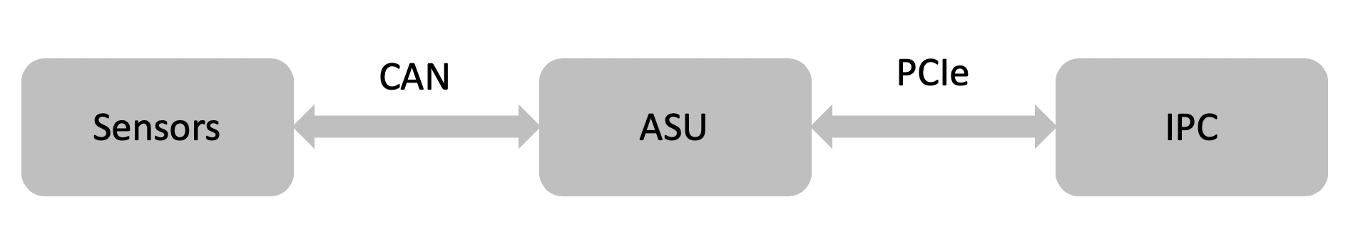
Apollo Sensor Unit (ASU) is designed to work with Industrial PC (IPC) to implement sensor fusion, vehicle control and network access in Apollo’s autonomous driving platform.
The ASU system provides sensor interfaces to collect data from various sensors, including cameras, Lidars, Radars, and Ultrasonic Sensors. The system also utilizes pulse per second (PPS) and GPRMC signals from GNSS receiver to implement data collection synchronization for the camera and LiDAR sensors.
The communication between the ASU and the IPC is through PCI Express Interface. ASU collects sensor data and passes to IPC via PCI Express Interface, and the IPC uses the ASU to send out Vehicle Control commands in the Controller Area Network (CAN) protocol.
In addition, Lidar connectivity via Ethernet, WWAN gateway via 4G LTE module, and WiFi access point via WiFi module will be enabled in the future releases.
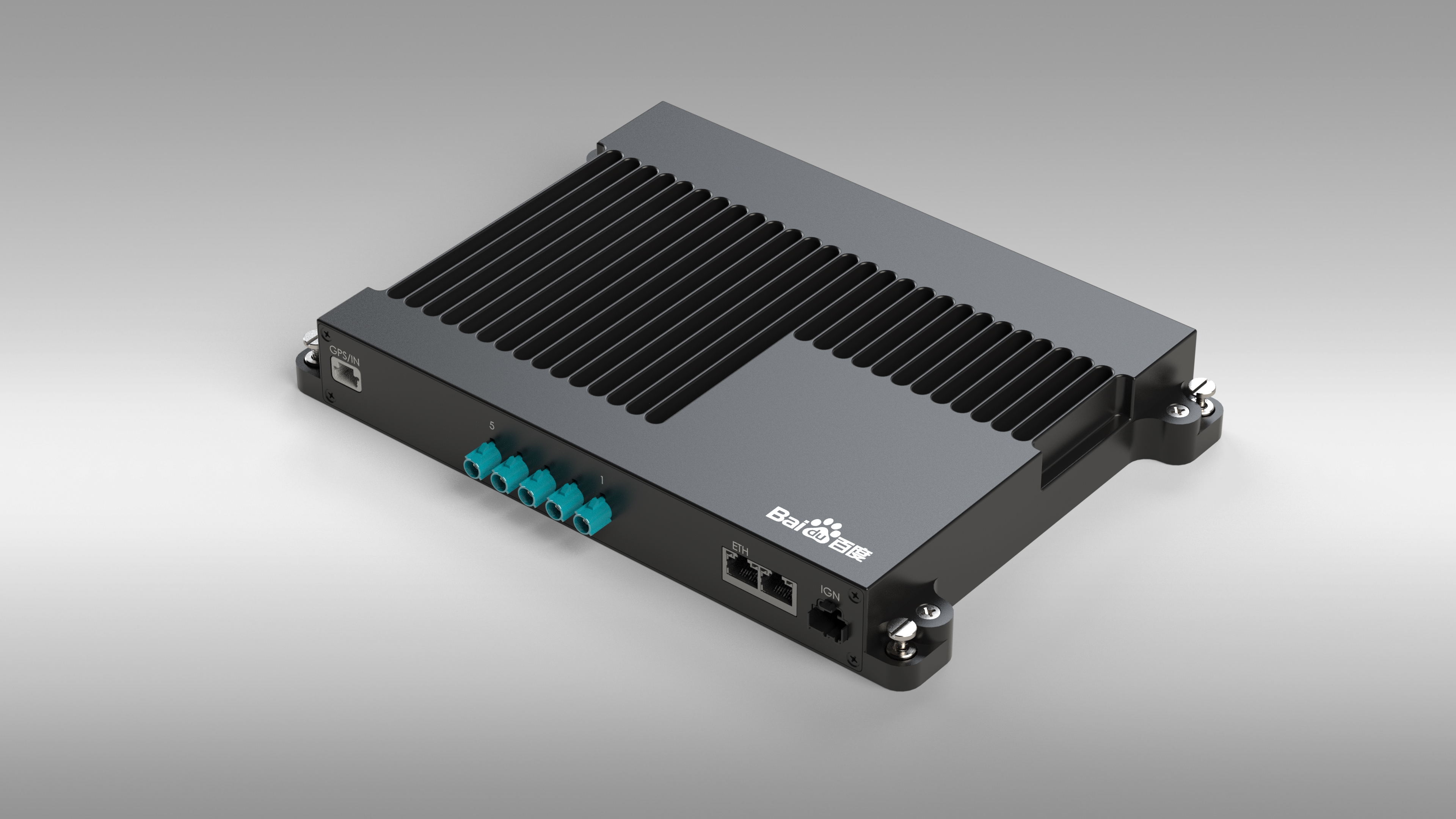
System Connectors
Front Panel Connectors
External GPS PPS / GPRMC Input Port
FAKRA Camera Data Input Port (5 ports)
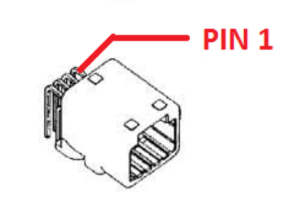
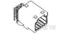
100 Base-TX/1000 Base-T Ethernet Port (2 Ports)
KL-15 (AKA Car Ignition) Signal Input Port
Rear Panel Connectors
General purpose UART port(reserved)
External PCI Express Port (Support X4 or X8) For connections to IPC, please use EXTN port.
GPS PPS/GPRMC Output Rectangular Port (3 Ports) for LiDAR
Power and PPS/GPRMC Cylindrical Output Port for Stereo Camera/LiDAR
CAN Bus (4 Ports)
Main Power Input Connector
Purchase Channels
The Apollo Sensor Unit is currently only provided to our Partners and certain developers. Questions regarding the availability and access to ASU should be directed to apollo-hw@baidu.com
Installation
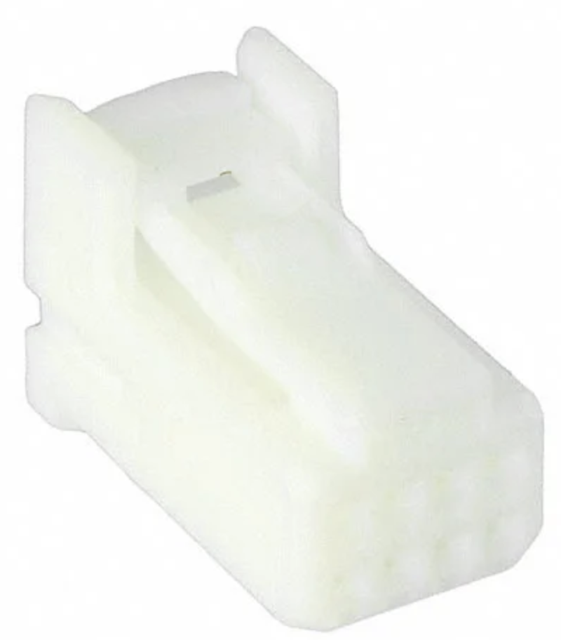
Power Cable
The main power is from vehicle battery, 9V ~ 36V, 120W.
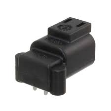
MFR
MPN
Description
TE Connectivity
DTF13-2P
DT RECP ASM
PIN #
NAME
I/O
Description
1
12V
PWR
12V (9V~36V, 120W)
2
GND
PWR
GROUND
FPD-Link III cameras.
There are 5 FAKRA connectors for FPD Link III cameras in ASU Front Panel labeled with 1~5, respectively, from right to left. The ASU can support up to 5 cameras by enabling Camera 1 ~ 5 whose deserializers (TI, DS90UB914ATRHSTQ1) convert FPD Link III signals into parallel data signals.
Camera #
I2C Address
Deserializer
1
0x60
DS90UB914ATRHSTQ1
2
0x61
DS90UB914ATRHSTQ1
3
0x62
DS90UB914ATRHSTQ1
4
0x63
DS90UB914ATRHSTQ1
5
0x64
DS90UB914ATRHSTQ1
GPS synchronization input channel
GPS synchronization input channel is using 1565749-1 from TE Connectivity as the connector. The connector information and the pinout are shown in the tables below.
MFR
MPN
Description
TE Connectivity
1565749-1
Automotive Connectors 025 CAP ASSY, 4 Pin
PIN #
NAME
I/O
Description
1
GPRMC
INPUT
GPRMC TX
2
NC
NC
NO CIRCUIT
3
GND
PWR
GROUND (the ground for PPS and GPRMC should be shorted on ground)
4
PPS
INPUT
Pulse per Second from GPS transceiver, 3.3V CMOS Signal
GPS synchronization output channels
ASU forwards the duplicated GPS PPS/GPRMC from external GPS to the customized 8 Pin connector. This connector provides 3 sets of PPS/GPRMC output for sensors that need to be synchronized, such as LiDARs, etc.
MFR
MPN
Description
TE Connectivity
1376350-2
Automotive Connectors 025 I/O CAP HSG ASSY, 8 Pin
PIN #
NAME
I/O
Description
1
GPRMC0
OUTPUT
Channel 0, GPRMC OUTPUT, RS-232 Signal
2
PPS0
OUTPUT
Pulse per Second from GPS transceiver, 3.3V CMOS Signal
3
GPRMC1
OUTPUT
Channel 1, GPRMC OUTPUT, RS-232 Signal
4
PPS1
OUTPUT
Pulse per Second from GPS transceiver, 3.3V CMOS Signal
5
GPRMC2
OUTPUT
Channel 2, GPRMC OUTPUT, RS-232 Signal
6
GND
PWR
GROUND
7
GND
PWR
GROUND
8
PPS2
OUTPUT
Pulse per Second from GPS transceiver, 3.3V CMOS Signal
CAN interface
The ASU provides 4 CAN Bus ports, the datapath is :
MFR
MPN
Description
TE Connectivity
1318772-2
Automotive Connectors 025 I/O CAP HSG ASSY, 12 Pin
PIN #
NAME
I/O
Description
1
CANH-0
INOUT
Channel 0, CANH
2
CANL-0
INOUT
Channel 0, CANL
3
GND
PWR
Ground
4
CANH-1
INOUT
Channel 1, CANH
5
CANL-1
INOUT
Channel 1, CANL
6
GND
PWR
Ground
7
CANH-2
INOUT
Channel 2, CANH
8
CANL-2
INOUT
Channel 2, CANL
9
GND
PWR
Ground
10
CANH-3
INOUT
Channel 3, CANH
11
CANL-3
INOUT
Channel 3, CANL
12
GND
PWR
Ground
GPS PPS / GPRMC Output Rectangular Port
The Connector provides 8 ports for 3 LiDARs
MFR
MPN
Description
Digi-Key
A121343-ND
025 I/O PLUG HSG ASSY 8P
PIN #
NAME
I/O
Description
1
GPRMC
OUT
GPRMC (ASU) -> Pin4 GPS_RXD_CNT (LiDAR 1)
2
PPS
OUT
PPS (ASU) -> Pin1 GPS_PULSE_CNT (LiDAR 1)
3
GPRMC
OUT
GPRMC (ASU) -> Pin4 GPS_RXD_CNT (LiDAR 2)
4
PPS
OUT
PPS (ASU) -> Pin1 GPS_PULSE_CNT (LiDAR 2)
5
GPRMC
OUT
GPRMC (ASU) -> Pin4 GPS_RXD_CNT (LiDAR 3)
6
GND
PWR
Ground (ASU) -> Pin3 GND (LiDAR 1,3)
7
GND
PWR
Ground (ASU) -> Pin3 GND (LiDAR 2)
8
PPS
OUT
PPS (ASU) -> Pin1 GPS_PULSE_CNT (LiDAR 3)
PPS/GPRMC Cylindrical Output Port for Stereo Camera/ LiDAR
The Connector provides 8 ports but we currently use only 3
MFR
MPN
Description
Digi-Key
APC1735-ND
CONN RCPT FMALE 8POS SOLDER CUP
PIN #
NAME
I/O
Description
6
PPS
OUT
PPS (ASU) -> Pin1 GPS_PULSE_CNT (LiDAR)
7
GPRMC
OUT
GPRMC (ASU) -> Pin4 GPS_RXD_CNT (LiDAR)
8
GND
PWR
Ground (ASU) -> Pin3 GND (LiDAR)
Disclaimer
This device is Apollo Platform Supported